
LEARNING TO PLAY LEGO WITH METAMATERIALS !
ERC Consolidator grant META-LEGO (2021-2026)
PROJECT OUTLINE
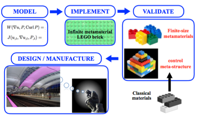
META-LEGO will bring the knowledge needed to design metamaterials/classical-materials structures that control elastic waves and recover energy. For this, I will develop, implement and validate a new paradigm for finite-size metamaterials’ modeling, by leveraging the relaxed-micromorphic model that I have contributed to pioneer.
The presence of boundaries in metamaterials strongly affects their response when coming in contact with mechanical loads. Yet, we still lack an exhaustive model to predict the static/dynamic response of finite-size metamaterials: current homogenization methods are unsuitable to provide a coherent transition from infinite- to finite-size metamaterials modeling. This prevents us from exploring realistic structures combining metamaterials’ and classical-materials’ bricks of finite size.
META-LEGO hypothesizes that the mechanical response of finite-size metamaterials can be explored going beyond classical homogenization. Instead, I will create an elastic- and inertia-augmented micromorphic model with embedded internal lengths to describe the main metamaterials’ fingerprint characteristics, such as anisotropy, dispersion, band-gaps, size-effects, etc.
To provide this paradigm shift, I will focus on 4 objectives:
1. Model metamaterials’ response under static/dynamic loads
2. Implement the model on infinite-size metamaterials
3. Validate the model on finite-size metamaterials
4. Design and manufacture metamaterials/classical-materials structures able to control elastic waves and recover energy
The reduced model’s structure (free of unnecessary parameters), coupled with well-posed boundary conditions, will allow us to unveil the static/dynamic response of both real and not-yet-existing metamaterials’ bricks of arbitrary size and shape. Playing LEGO with such bricks, we will be able to design and optimize surprising meta-structures, such as noise- and vibration-controlled railway stations, or meta-cities entirely protected from seismic waves.
HIRING NEW STAFF !
I am looking for skilled and motivated PhD students and Post-Doc researchers for positions starting immediately.
The research work will be carried out at TU Dortmund, Germany.
If you think to be convinced about your motivation, please contact me at angela.madeo@tu-dortmund.de, joining your CV, the bachelor's and master's transcripts, as well as a motivation letter.
Excellence and merit will be the only selection criteria!
The Continuum Mechanics team headed by Angela Madeo has started its work at TU Dortmund University.
We are still looking for an additional skilled and motivated PhD student!
META-LEGO Project's Progress
Model metamaterials’ response under static/dynamic loads
The direct finite element modeling of large-scale structures composed by unit cells of complex geometry is unfeasible due to the extremely tight meshing that is needed to correctly cover the entire microstructure. It is thus apparent that a homogenized model is required to use metamaterials in actual engineering designs. This motivates to model metamaterials' response with a micromorphic continuum allowing the presence of additional kinematical fields. One generalized continuum with great capability is the relaxed micromorphic model which uses the displacement u as well as an additional micro-distortion tensor P and its curvature part Curl P.
In recent work, we explicitly show how specific frequency- and wavenumber-dependent models can be transformed into their micromorphic counterparts. We propose a detailed procedure allowing us to pass from a frequency-dependent model to an associated micromorphic one by making use of suitable changes of variables and inverse Fourier transform. The newly obtained elastic- and inertia-augmented micromorphic model is such that no elastic parameter depends on frequency anymore. With the relaxed micromorphic model as a starting stepping stone, it is necessary to perform point-wise frequency or wavenumber fit of a given parameter (e.g. the density) and search for a suitable interpolation function that portrays the point-wise behavior precisely. This ensures that the corresponding extensions always allow for an improved representation of the underlying microstructured continuum. For example, Fig. 1 shows the improved performances achieved by an augmented micromorphic model obtained by varying a single parameter (µc). Applying the procedure to extra elastic and inertia parameters leads to further improved response.
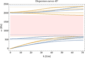

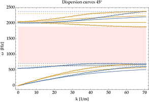
Figure 1: Left: the original dispersion fit. Right: the new improved dispersion relation of the new augmented micromorphic continuum based on a point-wise wavenumber fit of a single parameter (center) and its simple interpolation function (blue line).
Implement the model on infinite-size metamaterials
To prove the ability of micromorphic models for metamaterial modeling, several unit cells have been designed whose repetitions across one or two directions of space result in metamaterials which go beyond classical materials' mechanicals properties. In our case, these unit cells can inhibit wave propagation in particular frequency ranges which are known as frequency band-gaps, such phenomenon being mainly achieved by local resonances at the scale of the unit cell and enhanced by multiple reflections at the micro-scale for some designs (labyrinthine cells).
The fingerprint characterization of such unorthodox behavior, i.e. the computation of the dispersion curves of the metamaterial, can be made by a classical Bloch-Floquet analysis on the unit cell. Given this, a micromorphic homogenized continuum able to reproduce such complex mechanical behavior can be searched. In the case of the relaxed micromorphic model, the kinematic description usually consists of the vector displacement u and the non-symmetric micro-distortion second-order tensor P. The associated strain and kinetic energy (respectively W and K) densities (without curvature terms) are:
With the assumption that the elastic and micro-inertia tensors have the same class of symmetry as the considered cell, our generalized continuum for a tetragonal symmetric unit cell is completely determined by 12 independent coefficients. All these material parameters can be computed by the fitting of the dispersion curves obtained from the Bloch-Floquet analysis upon those of the unit cell, cf. Fig. 2.
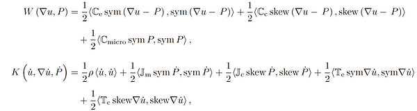
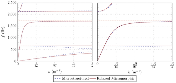
Figure 2: Left: Dispersion curves of the microstructured and the relaxed micromorphic systems along GX (propagation at 0°).
Right: Dispersion curves of the microstructured and the relaxed micromorphic systems along GM (propagation at 45°).
Validate the model on finite-size metamaterials
The presence of band-gaps in mechanical metamaterials is a widely known phenomenon and one of its many applications is the shielding of mechanical waves. We explore the capability of a reduced version, neglecting curvature terms, (see formula above) of the relaxed micromorphic continuum to model a microstructured material via simulations of finite-size domains. Using the aforementioned model, we can retrieve the response of the microstructured material for a wide range of frequencies with a significant reduction in the calculation time required for simulations.
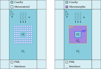
Figure 3: Schematic of a (single) metamaterial shield. Left: using the fully microstructued Cauchy and Right: the micromorphic continuum. All Cauchy domains have the properties of Titanium. A Perfectly Matched Layer surrounds the outermost Cauchy continuum.
The scattering pattern generated by the interaction of an incoming wave with the microstructured material is well captured by the homogenized model for a wide range of frequencies and for different angles of propagation. The importance of being able to accurately and efficiently model the scattered patterns is of a key importance for applications such as energy focusing, which can be harvested for a subsequent reuse. The reduced relaxed micromorphic model achieves a good agreement towards the microstructured material for stand-alone finite-size metamaterials, in the case of the individual shields, as well as in the simulations of multi-element and multi-shields configuration.
In particular, double-shield structures are simulated with the aim of combining two shields in order to have distinct but contiguous band-gap ranges, so that the effective band-gap of the metastructure can be considerably extended with respect to the one of a single shield. The micromorphic model is also tested for the response of more complex structures. For this, the shielding is divided into individual inner shields, surrounded by a peripheral shield. In this case, more complex interactions given the reflections with multiple obstacles is also captured by the reduced relaxed micromorphic model.

Figure 4: Solutions of time harmonic studies of a single shield device. The system is excited by complex pressure plane waves. The plots show the real part of the displacement field, normalized by the amplitude of the incoming wave. The shield has a thickness of 3 unit cells and the angle of incidence of the plane wave is 15 degrees. (first row ) microstructured material and (second row) equivalent micromorphic model for frequencies of ω 0.48 MHz, ω = 0.68 MHz, and ω = 0.92 MHz. The band-gap region of the considered metamaterial extends from 0.44 Hz to 1.06 Hz.
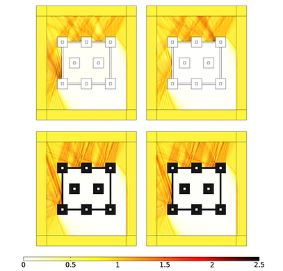
Figure 5: Peripheral shield 4 unit cells thick for an incident wave with a frequency of ω = 0.92 MHz and an incident angle of 30 degrees. Real (left) and imaginary (right) part of the normalized displacement for the (first row ) microstructured material and (second row ) equivalent micromorphic continuum. The thickness of each single shields is 10 unit cells.
As already mentioned before, metamaterials can be designed starting from their structural unit, the unit cell, and then constructed from the periodic repetition in space of the unit cell, see Fig. 6 (top). When the unit cell is designed appropriately, the corresponding metamaterial can show a band-gap at certain frequency ranges: this implies that the propagation of elastic/acoustic waves in these regions is completely prohibited. One can also understand that after the metamaterial's conception, a number of equivalent unit cell cuts can be identified that give rise to the same infinite metamaterial. An example of two of these equivalent unit cells can be seen in Fig. 6 highlighted with orange color: unit cell α (bottom left) and unit cell β (bottom right) which have a distinct shape, in particular on the edges.
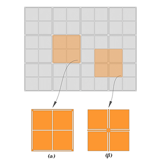
Figure 6: The constructed metamaterial (top) and two equivalent unit cell cuts that can be identified (bottom: unit cell α on the left and βon the right).
For the calculation of the dispersion diagrams, which are the diagrams that predict the band-gap, it is always assumed that the metamaterial is infinitely big and therefore that it has no boundaries (or equivalently, an infinite number of unit cells is used for its construction). However, this is not the case for real applications where the metamaterial has a finite size and thus ultimately has a boundary. Under this observation, one can think that the choice of unit cell cut matters in terms of boundary effects. The response of two finite-size specimens constructed from an equivalent unit cell but different cuts and the corresponding reduced relaxed micromorphic model simulation are compared in Fig. 7 for a frequency of 1000 Hz. The micromorphic model predicts well the overall metastructural response. Some localized boundary effects arising from one cell's cut and not from the other could be taken into account by introducing internal lengths or extra boundary contributions in the micromorphic framework.
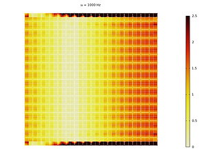
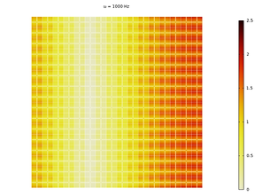
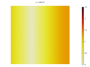
Figure 7: Displacement field comparison between unit cell α (left), unit cell β (middle) and the reduced relaxed micromorphic model (right) for the same specimen size and the same frequency.
Design and manufacture metamaterials/classical-materials structures able to control elastic waves and recover energy
The shift of the band-gap to even lower frequencies of the labyrinth cell was intended in optimization studies. Geometric parameters like the frame thickness were considered as well as the use of central mass in the cell for which different materials were tested. The use of a thinner frame and the increase of the central mass prove to be solutions to decrease the starting frequency of the band-gap. This is an example of how a stiffness reduction and a mass increase respectively can be used as means to influence the location of the band-gap. The closing frequency of the band-gap also decreases in both cases, but the band-gap stays reasonably big considering the intended low-frequency application of the metamaterial (Fig. 8).
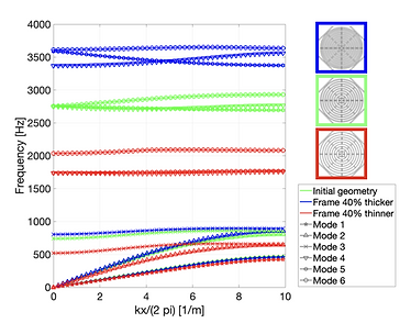
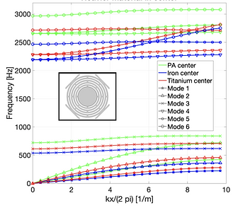
Figure 8: Influence of frame thickness (left) and central mass material (right) on the dispersion diagrams.
The dispersion diagrams of the micro-structured labyrinth cell were obtained in 3-dimensional numerical studies. Since the additional degrees of freedom lead to the appearance of additional dispersion curves, the aim of this study was to check if the band-gap spanned the same frequencies as in the 2D simulations. In order to be close to the experimental conditions, the periodicity was conserved in plane and the out-of-plane surface was left free to move. In the initially targeted configuration, the band-gap is invaded by two out-of-plane modes. Parametric studies showed, that the dispersion relation of these modes depends on the thickness of the structure (Fig. 9). Therefore, the frequency range, in which the band-gap is influenced can be limited by choosing an appropriate thickness. Experimental tests with structures built with unit cells having a optimized thickness are planned soon.
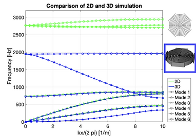

Figure 9: Comparison of the first six dispersion relations obtained from 2D plane strain and 3D simulations (left) and evolution of modes 5 and 6 with the cell thickness t = 8 mm (right).
Based on the labyrinth cell, different meta-material specimens were manufactured for vibroacoustic testing in an impedance tube. Matrices of 2x1 and 2x3 cells were cut out of Plexiglas and glued to gypsum plates in a sandwich configuration. The different sizes of the matrices and three different arrangements of the matrices between the plates lead to overall six specimens for the tests. A transparent square-sectioned impedance tube was manufactured for the tests which will soon be performed at the LTDS of École Centrale de Lyon in France via subcontracting. The specimens are placed in a demountable specimen holder, acoustic waves in different frequency ranges are created by a loudspeaker and the sound absorption is obtained from the pressure measurement with the four microphone method (Fig. 10). Those tests will allow to promote the broad public dissemination of our metastructural designs and can also serve as a first experimental validation of our modeling, simulation and design tools.
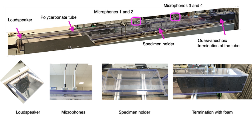
Figure 10: Experimental setup - impedance tube equipped with four microphones for pressure measurements via the four microphone method.